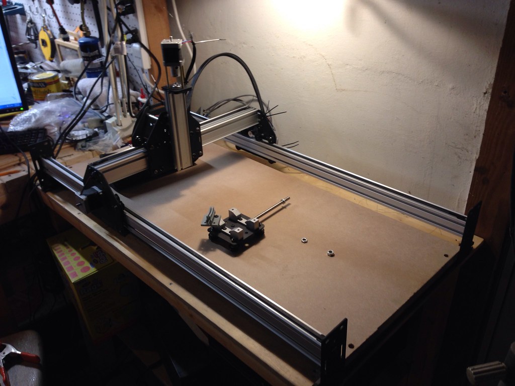
Behold: My extended Shapeoko2
My most pressing concern was mounting the Spindle to the z-axis carriage, but in thinking about the problem I got a little bit ambitious. I came up with some goals for my eventual design:
- Mount must hold the spindle securely on the z-axis
- Mounted spindle must clear the motor mount at the top of the z-axis.
- Mount must fit onto the existing z carrage and not add undue angular load to the z-axis.
- Mount must be 3D printable and require only minimal hardware to install.
- Mount features must be sized correctly after accounting for ABS shrinkage.
In addition to these I identified some optional goals that I would shoot for:
- Mount may hold a laser diode for help with homing.
- Mount may integrate a dust-collection hookup.
- Mount may integrate a compressed-air hookup for cooling.
- Mount may manage spindle electrical connections including power and coolant and low-voltage.
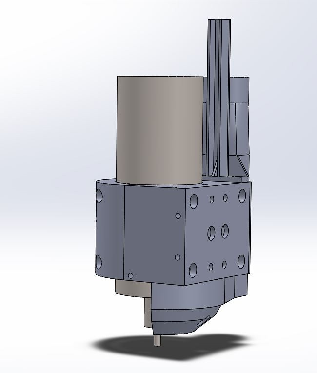
Modular 65mm Spindle Mount for Shapeoko2!

Initial Rendering Including the mount, the dust collection attachment and the dust collection foot!

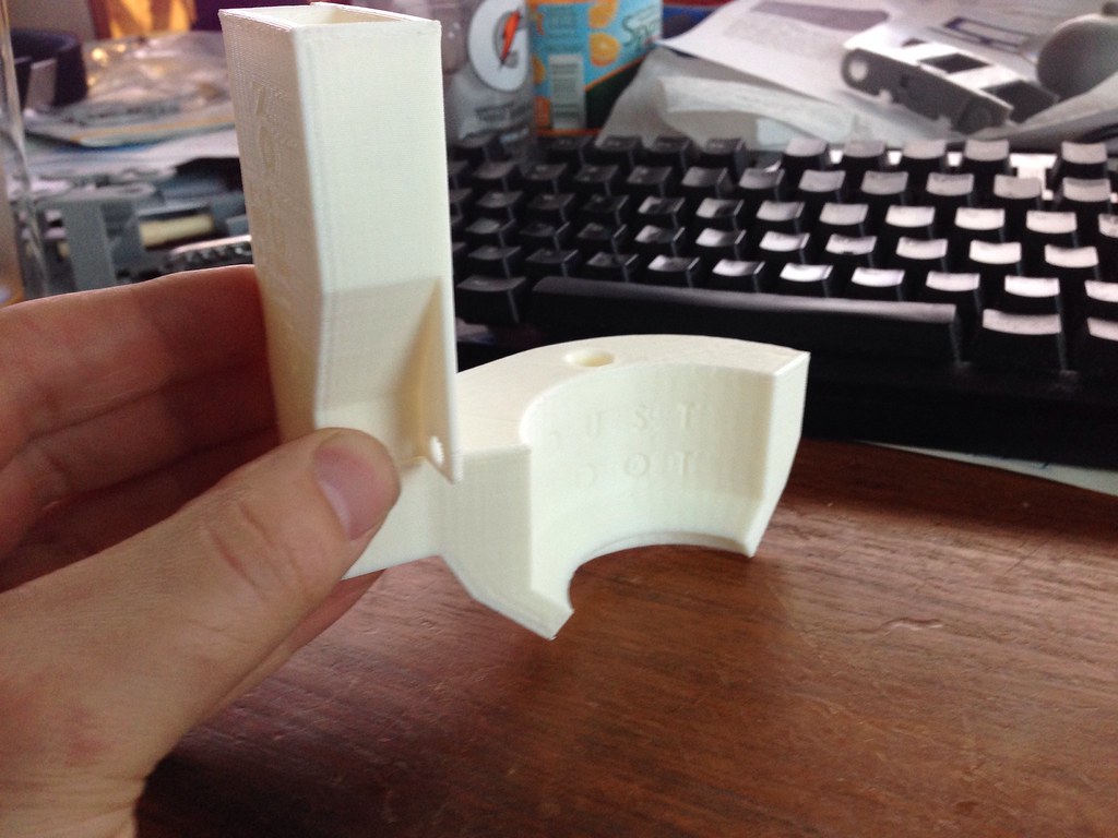
The first test print of the mount
The first test print taught me a lot about the way ABS shrinks after printing. Pretty much every dimension had to be enlarged by at least 1mm. Tight holes were tappable, but the stress from tapping resulted in layer delamination which weakens everything. I also discovered that the recessed bolt holes in the back of the mount were not sufficiently recessed. This caused the head of the M5 pan-head bolts to interfere with the spindle mount.
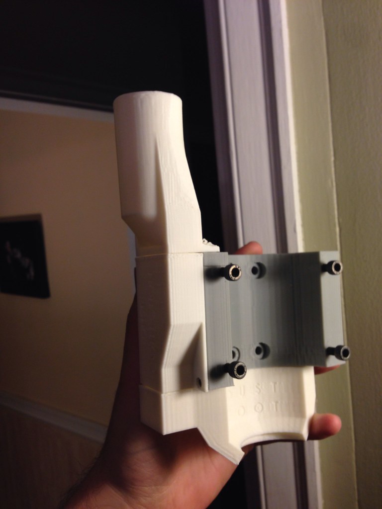
The good news is that the first test body fit on the z-carriage nicely and, most importantly, the spindle clears the bearing mount at the top of the lead-screw. This allows for maximum z-axis range. Something distinctly lacking in the factory tool-mount.
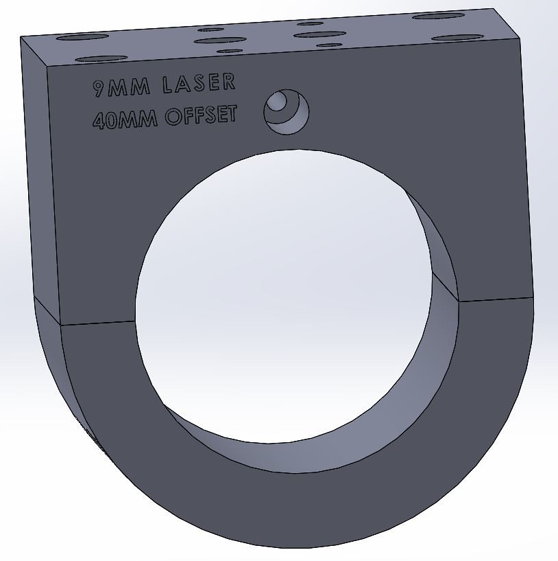
The bottom of the Spindle Mount showing the laser setting
In addition to holding the spindle the mount body also has a 9mm recessed opening for a Laser emitting diode. A 9mm laser diode can be be easily added and used for aligning the spindle. For easy offsetting, the center of the laser diode is located 40mm to the rear of the center of the spindle.
Having made these changes to the model I set about designing a dust-collection attachment. A key goal of the dust collection attachment is to that have as small a footprint as possible. A large dust collector effectively reduces the working area of the tool. The attachment needs to be modular in a way that allows for easy cleaning and for attachment to a variety of different vacuum systems. In addition the module needed to be easily 3D printable without support structures. To this end I broke the DC system in to three parts.

The Dust Collection Attachment (left) and Dust Foot (right)
The "Dust Collection Attachment" bolts securely to the side of the Mount body. This is the most-secure (and most-permanent) part of the dust collection system. The job of this component is to act as a middle man bringing suction down from the hose adapter through to the dust foot.
The Dust Foot "snapped" onto the Attachment
The "Dust Foot" snaps on to the bottom of the Attachment using a flexible plastic snap-fit. This provides two functions. First, it allows the Dust Foot to be easily detached for cleaning, for changing bits or simply to get it out of the way. It also prevents damage in a situation where an operator inadvertently crashes the foot into the work-piece.
The Dust Foot has a pass-through hole to allow the alignment laser to pass through the foot. This is a bit lame as it restricts air-flow through the dust foot. Future versions will probably move the laser to another position.
The Vacuum Adapter clipped to the top of the Dust Collection Attachment
The third piece of the Dust Collection system is the "Vacuum Adapter". At the moment this adapter fits the hose of the shop-vac at my house (which has an OD of around 1.25"), however I plan on making several different adapters to fit 1-5/8" and 2-1/2" hoses. The Vacuum adapter serves two purposes: First it attaches the Dust Collection manifold to your shop-vac, and second it will serve as a utility pole for managing cables and tubes exiting the top of the spindle. This function is shown in the rendering below.
The utility mast to the right of the spindle body will eventually feature wires and zipties
The added angular load imparted on the "utility pole" and "Vacuum Adapter" require that the adapter be screw-mounted to the top of the mount body. Tapped mounting holes are available on both sides of the body so that the system can be mounted "ambidextrously."
So that's it! The bit thing I'm waiting for now is the actual spindle! Once I get it in hand I can do a real fit-test and start to really finish the design work!
The design is available for free download on Thingiverse.
The system is a work in progress and I'm looking for feedback from anyone interested in this!